| |
|
DIGITAL HOLOGRAM PORTRATIS #4 -- 2/22/04
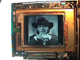
Despite my rush home tonight with several optical post extenders, it looks like just one more step to take care of before actually getting to a test shot. Above is an internal view of the Proxima Ovation 846 partially disassembled. For information purposes, the LCD panel is ID'd as a SHARP LQ10P341. Before moving any further along this path, I decided to remove the raw LCD panel held within. The panel itself measures 8.5 inches x 6.5 inches (image area) . . . and only a quarter-inch thin . . . which will take up much less room in the holographic table set-up then the entirely assembled unit (quite large). In order to feed this panel once totally removed, I will have to make two 24-pin ribbon cable extensions that will run from the electronic circuits (which I will locate off the table), to the panel itself (located on the table). At present, and as above, I have to have it still cradled within the lower half of the housing in order to feed any images to it, since the ribbon cables measure less than 2 inches in length from the circuit board to the panel. The image above is my usual, and familiar test image -- this time rear-illuminated on a 5000k light table in the studio. Until I am able to put the extension ribbon cables together, I prefer to have it lying flat and secure on a solid surface, rather than standing upright on the holography table (all screws are removed) -- so no laser illumination this time around.
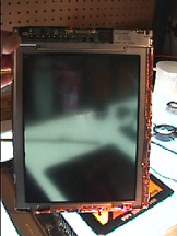
The above photo shows the raw LCD panel removed from the housing. This is how it will be used on the holography table -- with ribbon cables running to the electronics. A benefit to this is not only the reduced overall size -- but also the fact that the optical components can now be closer to the table surface, no longer needing to raise them up so as to hit midpoint through the screen. It's also a nice size for shooting 8 x 10's later on down the line -- leaving a little more space than would be needed around the perimeter of an 8 x 10 hologram, however. Please take note to the blurring effect of the panel screen. Things are not looking good to use a second LCD panel for the animated slits sync'd to the images -- as the master plate will have to "look" through this clear area of the panel (each slit). This obviously would severely blur any image being displayed on the image LCD panel -- according to the viewpoint of the master hologram. I also did a few polarization tests tonight as well. Even with the screen clear, it completely takes the transmitted laser light from full intensity to no transmission at all when rotated. This is not a problem per se, since the master hologram will be facing the panel with its emulsion side. If the master plate were facing the panel with its glass side, one would not only have to be concerned with obtaining full-transmission through the panel, but also full transmission through the hologram plate glass substrate at the same time. Thank goodness for small miracles. However, this is not out of the woods yet -- as the "effect" that the panel has on polarization still needs to be determined (relative to the reference beam). Everything could "look" as if it's OK . . . then wind up getting extremely dim results . . . if anything at all.
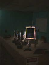
Above is a shot of the panel being held temporarily in place on the holography table for the photo -- completely removed from its housing. If you compare the size now to the size from previous full-assembly photos you'll be able to make a comparison as to what benefit its removal has created. When working with the panel, it will be held in place much lower and closer to the table surface. You can also see the optical post height extenders in place that I was going to use to get the beam up to the needed height. These are no longer needed (second miracle of the night).
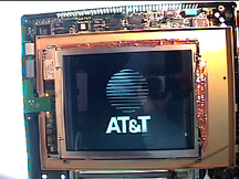
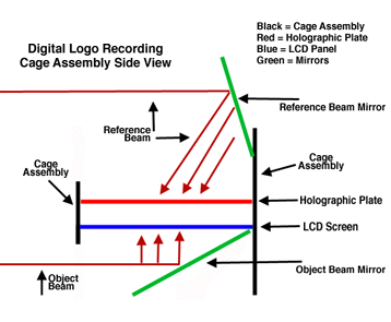
As mentioned early on, this is not limited only to portraits of people. Making holograms of objects that could not be possible due to having to have the actual object in the lab are possible as well . . . a car, house, monument, spacecraft at a museum, etc. Another application is for corporate logos. I used to do these direct from film -- drum scanning the logo, outputing the logo via RIP (raster image processor) laser imagesetter, then taking the resulting film and attaching it directly behind a piece of ground glass and rear-illuminating it. Although the image would not be 3-dimensional per se, to compensate for this lack of dimensionality I would record the logo as a 2-D real image, which would then float approx. 8 - 10 inches (or more) in front of the finished hologram when displayed. With the LCD screen, logos can be sent directly from the workstation and displayed for recording. AT&T was one of the clients that I did holograms for, so I'm using their logo here for display on the LCD panel for this photo. The holograms that I did for them were awards given to recipients of their "Go for the Gold" incentive program. I include this here as yet another example of what can be done -- although certainly not portrait-based. A simple one-step recording "cage" can be made as illustrated (simply) below:
A similar assembly has been noted and used in the past for recording single beam reflection holograms, and also single-beam, contact-copy, master to copy transfers. With this assembly, there is an actual object beam (to the LCD panel) and reference beam (to the holographic plate) -- so it's essentially a split-beam setup, albeit a very compact one (and portable too). Each mirror provides a different angle -- the object mirror sends the diverged object beam directly through the panel, and the reference mirror sends the diverged reference beam to the holographic plate at brewster angle. In order for the resulting image to "float in space" the emulsion should be up, and the image reversed both horizontally and vertically on the LCD panel -- or what is commonly known in the trade as "flopped". The distance from the panel to the holo plate would be the amount of distance that the logo would float in front of the finished and displayed hologram. Quite simple actually considering the final effect. This creates your typical, "Oh look, I can pass my hand right through it", kind of hologram. A single beam method could be applied here as well by diverging the beam enough to hit both the reference and object mirrors. This single beam would then act as separate reference and object beams -- although any adjustment of beam ratios would not be possible. That being said, I will also note that some of the brightest logo holograms were those that were closer to 1:1 ratio, rather than the suggested 2:1 ratio for direct-from-object, split-beam reflection holograms (1.5:1 is recommended for H1 to H2 transfers). And, last but certainly not least, all of the above can be simply achieved by scanning the beam via galvometer scanners. If you have one scanning unit, you can pass the beam through a cylindrical lens (make one out of a mineral oil filled test tube) and then use your scan head to scan the resulting line across the two mirrors, or if you have two scanning heads, use one to form the line and the other to move the line across the mirrors. Just remember to keep your vibrating scanning heads off the table. Since this is a single-beam method, only the cage and its contents need to be isolated anyway. I have a double-head BeamScan XYP-1000 programmable unit here in the lab. Once I get the ribbon cable extensions completed, I'll move on to setting up for the first test shot. I have to order a few parts on Monday. Now, if you'll pardon me, I'm going to go spend some time with the lady in the top photo. More reports coming up.
|