
| |
|
DIGITAL HOLOGRAM PORTRAITS #6 -- 4/26/04
NOTE: A quick update note from Emails that I have been receiving. Just to clarify, ground glass is still used with the LCD panel. It is placed in BACK of the LCD panel to diffuse the spread laser light traveling through the panel. I have found that if you do not use some sort of diffuser, the point-source light from the expanding lens becomes visible through any clear area of your image appearing on the panel -- as the panel, in and of itself, does not diffuse the point source light sufficiently to overcome this effect/drawback. With the diffuser (such as ground glass) this effect is gone entirely. I am also aware (so far at least) that a diffuser is not noted in the literature on LCD techniques, along with other preparatory steps such as the proper calibration of the LCD panel (output) to the workstation monitor (image editing/proofing). I do not know why -- but it appears that many other items are not noted, or noted in detail, as well that I've been attempting to include here (such as polarization adjustment for maximum transmission of laser light). These important items of consideration, along with the calibration information I am including below, may well be several reasons why LCD techniques have received less than favorable reviews along the way. This does not have to be the case at all (as we're finding out). So, to clarify once again, yes . . . the ground glass is used to diffuse the laser light and is placed behind the LCD panel as close to the panel as possible. The set-up would go: expanding lens or spatial filter, ground glass, LCD panel, master plate holder. My apologies for missing the boat on this important point in the instructions so far. On to the previous post:
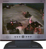
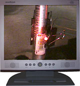
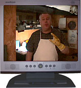
I am writing this beforehand and will add everything else later (pics and vid, etc.). Tonight I'm going to shoot the first laser transmission test shot, and will be doing so with a laser diode and all home-made optical components and older-style sand table. This will be a single-image shot first time out of the gate here. The table is already set-up and settled, and has been that way, in-progress, throughout much of the past few weeks for LCD panel calibration (see below). This will be the do-or-die test, and it all comes down to this. If an acceptable laser transmission master cannot be created, similiar in quality to film-based method, it is all over tonight. Every precaution and anticipated problem has been troubleshooted in advance. With what talents and abilities I have gained over the years in holography, I have nothing left to add with this. As for the use of an LCD, and along with some background information, this LCD image recording technology has been available, and already used within holography, for years -- going back to the 1980's. Hendrik Gerritsen worked with an LCD for stereograms and received patent #4,878,717 in 1989. His work was with reflecting laser light off of the panel (with a white background placed behind). John Iovine worked with an LCD for stereograms and received a patent #4,964,684 in 1990. His work was with transmitting laser light through the panel -- which became, and remains, the standard proceedure. Since that time, most if not all of the computer generated holograms that have been made have been made with LCD's, or with scanning micro-mirror devices or similar modes of output. Plasma displays are also an option worth exploring, and I do not believe are covered in any literature as yet. Myself, I'm looking into HD (high definition) plasma output panels. I believe that it is only a matter of time before the LCD method is retired for good. If you have any further information on this history, please send it along so that it can be noted. John Iovine, noted above, has been following our progress, and sends his compliments of "great job", his best wishes of "keep up the good work" and also this tip: "I can offer your readers a tip on this process. First you don't need an expensive LCD panel. You can tell your readers they can use a inexpensive LCD TV. The only modification required is removing the EL panel behind the LCD screen. The TV's LCD screen is really transparent. I haven't played around with this in years so I don't know if this mod has become more difficult." John also has a book titled "Holography for Photographers (1999)" in which he says has information on doing hologram portraits that is similar to what is being done here. He didn't say in the Email whether it was with standard photography or LCD (or both). The book appears to be out of print (according to Amazon.com) but can be purchased used there. John is also the author of "Homemade Holograms". As for what is being done here and its own history and evolution, I began doing 35mm photography stereogram portraits in the early 90's and reported on it in The HoloGram newsletter and LASERnews. It was (and is as noted earlier) a variation on the work of DeBitetto from 1969 (Holographic Panoramic Stereograms Synthesized from White Light Recordings) which is the classic foundational reference (at least it was for me), the "LeslieGram" noted in The Holography Handbook from 1983 when I finally started my own lab, the Huff/Fusek and Molteni papers from the SPIE Proceedings of 1982, and a stereo pair experiment from the Newport Research holography guide (circa 1983). Since I had to do these "by hand", i.e. slit changes and image registration -- I found that the usual way, noted in the literature, of doing them with the projected images in-line with the slits would not work -- the results were very much below acceptable standards. So I rearranged the recording geometries, applied pre-press methods of registration by eye/hand, and made the resulting hologram more of a light-directing holographic optical element placing the reconstruction of the physical slit area out of line-of-sight. This allowed for less tolerances of slit registration -- although still requiring tight registration of each image. Long throws of laser light replaced the need for collimating optics, and eliminating the usual liquid-filled lens also helped to ease the equipment requirements. Benton provided the math on what these long-throw distances would be in the literature for getting maximum collimation without the use of collimating optics. Turned out that the results were now more on the visual line of a pulsed-portrait in nature -- in that the viewer did not get a sense of slit recordings, and that the image was "still", rather than displaying motion (due to the low number of slits/images required with the method). Hopefully this fills in the gaps on where we are and how we got here. And, as you'll see below, it's much more than just placing an LCD on the table to take the place of projected images . . . as good an idea as it seemed "as is" so long ago. I believe that many of the shortfalls related to the usage of LCD panels can be attributed, if only in part (but a large part), to what I will present below on output device calibration. Now, on to our hologram. Everything for this shot is the same as doing this with 35mm film, except that we're using a computer workstation to supply an LCD panel with our test image. I'm assuming that you have already reviewed these previous sections, so I am going to make this entry centered around calibration. Watch the video for a more detailed report of tonight's shoot. Pictures on this page are frame grabs from the video. OK, now on to calibration . . .
In between weekend workshops (hello all) and two and half weeks of passing three kidney stones (ouch! is an understatement), I've been doing CALIBRATION checks and adjustments. If you carry nothing else away with you from all of these reports and updates, remember this: I have found that CALIBRATION BETWEEN YOUR WORKSTATION MONITOR AND THE LCD PANEL IS THE *MOST* IMPORTANT TASK. Do not expect your perfectly adjusted workstation image to remain that way once it has been transferred to the LCD panel. ESPECIALLY when attempting to maintain shadow and highlight detail.
I will take a few moments to go over this further: First, your workstation monitor should be calibrated properly to begin with. There are calibration sensors that suction-cup to a monitor to do this, along with the associated software . . . or if you do not have the luxury of having one, adjusting your monitor to properly show a grey-scale test image, by eye, is the next best thing. There are plenty of resources on the Net to familiarize you with this process. Next, you must then run the same greyscale test image on the LCD panel display. This is where it gets a little tricky, since you want the test pattern on the LCD screen to match the results of your workstation output -- and if it doesn't, you must then compensate between the two.
What we have to do is make the numbers/readings match. Assuming that you'll be working on your workstation monitor for image adjustment, we'll use those numbers (once calibrated) as the master set. In other words, we then need to adjust the LCD panel to match the workstation monitor (not the other way around). First, assuming our workstation monitor is calibrated properly (and do so if not), we will begin by making brightness and contrasts adjustments to the test pattern on the LCD screen so that the greyscale test image readily shows all percentages steps. Once that has been achieved, we then take individual readings of each percentage step, and compared those values to the values obtained from the workstation monitor. Since we're involved with holography, many of us have a photometer that we use for determining exposure times. Use this. I use the Science & Mechanics Photometer and probe. Write down each of the readings for all of the percentage steps for both the monitor and the LCD panel. You'll notice a difference between certain step readings on the LCD panel, and those recorded from your workstation monitor. That's fine . . . and expected. Also note that we're trying to determine RELATIVE readings -- not actual intensity readings. We're looking for "drop-outs" and "pushing" values.
Now, in order to make sure that the LCD provides the same quality image that we viewed on our monitors, throughout all percetage steps, we must go into a photo editing program such as Adobe PhotoShop, and set up custom curve values according to the relative differences for each of the greyscale steps between the panel and monitor. Save these curve adjustments, as they will now become a master file for compensating the differences -- and will be applied to each and every image that we send to the panel from here on out. Once this image has the custom curves applied to it, the values will compenstate according to our greyscale test image results. Think of it like an audio equalizer, in that certain frequencies are adjusted according to a reading of the room acoustics. In our case here, the custom curves applied to the image is the equalizer, and the LCD Panel is the acoustical profile of the listening room. Best I can do. If you have any questions, it would be good to resource the Net for learning how to do calibration between to output devices. As I said above, without this relative calibration, what you see is NOT going to be what you get -- and what you get is not going to be very good.
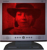
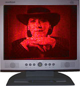
I strongly believe that this information makes all the difference in the world -- and seeing is believing -- at least by eye, here in person in the lab. Now is the time to watch the video if you choose to do so. As you can probably tell from the video frame grabs which I added tonight, the hologram was a success. Next steps will be to set up a another laser-transmission hologram test -- this time utilizing all eight slit exposures for a three-dimensional master hologram (only one image was used for tonights initial mastering test). I am in the process of choosing a digital camera for this next master hologram test. The final test will be a reflection copy transfer. So . . . two more to go. Camera shopping time.
Next Day Notes:
CONTRAST (black level): About the same. I should also note (which I failed to do so far) that this was carried out with: 35mW 658nm laser diode (running at 28mW at 650nm), 75/25 beam splitter (obj/ref), just standard objective lenses this time (no spatial filtering), 10 second exposure on AGFA8E75HD plate, with pyrochrome processing. Pyrochrome is not my first choice for mastering, but was already using it for recent workshops and just continued with it. Usually I use the standard D19 at 4:1 ratio dilution for working solution (distilled water/developer), and no bleaching. Web Video Notes: As with the first video, this second video is approx. 2.6 MB in file size and 5 minutes in length. If you are accessing from a long distance, you may experience rebuffering due to congestion -- especially if you are on a dial-up connection -- and I know that many of you still are. Those of you who are closer to the Philadelphia, PA area, and/or have broadband should experience the best playback. As a result, I have compromised by doing the best image quality, yet a small video window size, to best serve everyone. You will need the FREE RealPlayer from RealNetworks in order to watch this video. If you do not have the player, you may obtain it here. They offer a player for sale, so you'll have to look closely for the free one.
 Click above to watch video.
|