
| |
|
MODULE THREE: SHOOTING THE MASTER updated 1/23/04
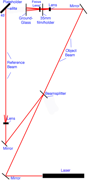
Module Three RealAudio: The above audio is in RealAudio format. You will need the free RealAudio player to listen. If you do not have the player, you can download it HERE. The above represents the table geometry for shooting the laser transmission hologram -- which I will refer to as simply the standard "H1" designation from now on. Much detail will be provided in this modules audio segment, which is now uploaded above. For now, a brief text overview of the diagram (but please listen to the audio file!):
BEAM MEASUREMENTS:
REFERENCE BEAM: 23 inches /80 inches
80 inches from mirror to plateholder
35 inches from mirror to plateholder
The diagram is set up to reflect an 4 x 8-foot holotable. We are going to utilize the entire surface area for our set-ups. One reason for this is to provide long throws of the reference beam, thus reducing the need for collimating optics. If you already have collimating optics that you can utilize in this set-up, use them by all means. You may adjust beam path lengths according to the f-value of your collimating mirror, but please maintain the 45-degree angle of the reference beam incident to the H1 plateholder. For shooting the eventual reflection copy, the above table geometric relationship between the reference beam, H1 plateholder and ground glass screen is going to "flip" around, and all angles will be used once again -- and must mirror the initial set-up. More on this later of course. Viewing the table layout should be fairly self-explanatory for holographers with split-beam experience . . . although this would be a rather useless set-up for shooting a laser transmission hologram of an object with the object beam coming in the way it does. However, the object beam in our case is actually performing the same function as a slide projector lamp, in that its main function is to project the frames from our photography onto the ground glass screen. The divergence of the beam once it passed through the lens, then through the slide, will act as an enlarger. So the image on the ground glass will be adjustable in size according to the placement (and focal length) of the lens used. I use a spatial filter in my set-up with a 20x objective. The lens that is used after the slide (the camera lens) acts strictly as a focusing mechanism . . . although it will also effect image size on the ground glass so its placement must be determined by trial-and-error. Between moving your expanding lens, along with the camera lens, you should be able to achieve the correct size and focus on the ground glass. I would suggest that you mark these measurements down for future reference. If you were to now look through the H1 plateholder, you would see your frame on the ground glass . . . similar to a television screen. It is important to have the image projected in the correct orientation -- which is on its side. More on this later, but for all practical purposes since this is a portrait, we are actually shooting the H1 (and reflection copy (H2) later) on its side. The side reference beams are actually overhead reference beams on their sides. Photos will be uploaded showing the proper orientation as you would look through the plateholder, since if oriented incorrectly, your person will be upside down or sideways in the final hologram. QUICK TIP: Not included in the audio file: Once you have your mirrors, beamsplitter and plateholder in place, and before adding the lenses, 35mm frame holder and ground glass, put a white card into the master plateholder. Once the card is in place, adjust your reference mirror so that the reference beam dot hits the white card right in the center. Then do the same with the object beam dot. The two dots (reference and object) should now be one dot on the white card. This will insure that your set-up is aligned properly. Now you can begin to add your other components. And, don't forget . . . the reference beam and the object beam paths should always measure the same distance from the beamsplitter to the plateholder.
|
 LISTEN HERE